Analysis of Electromagnetic Interference in S-Band Doppler Radar Systems Being Used by IMD
P. Singh*, B.K. Kanaujiya, R. Kumar, and S. Singh
Meteorological Watch Office, India Meteorological Department, IGI Airport, New Delhi, India
Submitted on 26 November 2024; Accepted on 12 February 2025; Published on 17 March 2025
To cite this article: P. Singh, B.K. Kanaujiya, R. Kumar, and S. Singh, “Analysis of Electromagnetic Interference in S-Band Doppler Radar Systems Being Used by IMD,” Insight. Electr. Electron. Eng., vol. 2, no. 1, pp. 1-8, 2025.
Copyright: 
Abstract
This study investigates the issue of electromagnetic interference (EMI) in Doppler weather radar (DWR) systems employed by the India Meteorological Department (IMD). IMD utilizes a range of radar systems operating in S-band, C-band, and X-band frequencies to monitor precipitation, intensity, movement, and type (rain, hail, snow, etc.). These radar systems rely on the extrapolation of radar backscattered echoes and numerical model predictions, integrated with radar data, to forecast weather phenomena and location. Notably, transmitted signals are quite powerful (800 kW) and the received echo signal by the radar antenna is relatively weak (~3-16 W). Raindrops are typically 0.5–5 mm in diameter with a distance between two raindrops ~5 cm, due to which, a small fraction of transmitted energy hits the raindrops and is scattered back. Consequently, a weather radar system performs its functions with high sensitivity while navigating for the target in the dynamically changing electromagnetic environment. However, as electricity within a circuit is never absolutely enclosed, electronic devices inevitably emit some amount of electromagnetic radiation, which can interfere with weather radar signals when emitted at the same or near close frequency. This interference can disrupt measurements and distort output images, potentially displaying spokes, spots, or stripes that limit the value of radar pictures. Moreover, electromagnetic emissions within the transmitter chain can impact the transmitter's performance by introducing spurious and harmonics in the pulse shape. This paper examines the nature of the problem faced by S-band Doppler radar systems used by IMD across India and discusses potential techniques for mitigating the issue.
Keywords: electromagnetic interference; radar systems; frequency; antenna
Abbreviations: EMI: electromagnetic interference; DWR: Doppler weather radar; IMD: India Meteorological Department; RFI: radio-frequency interference; EMC: electromagnetic compatibility; PPI: plan position indicator; ASR: airport surveillance radar; IRIS: Integrated Radar Imaging System
1. Introduction
Meteorological radars are singularly vital instruments for real-time detection, measurement, and monitoring of precipitation and wind conditions [1]. Their capabilities extend to observing rainfall rate distributions, cumulative rainfall over time, horizontal wind profiles, cyclone and tornado signatures, maximum wind speeds in cyclones, wind shear and turbulence, and the likelihood of severe weather and hail [2]. The digital data generated by meteorological radars can be integrated into computer models to predict weather trends, alert meteorologists to impending storms and severe weather [3], and inform numerical weather prediction models for nowcasting (up to 2–3 hours), short-term (up to 1–2 days), and medium-term forecasting (up to 5 days).
Furthermore, rain accumulation data is utilized in hydrological processes such as flood monitoring and dam catchment areas. Meteorological radar networks serve as the final line of defense against loss of life and property in flash floods and severe storm events.
Additionally, weather radars enhance aviation safety and the efficiency of the air transport industry, as pilots rely on airborne weather radar to assess weather intensity ahead of their aircraft. Notably, meteorological radars operate under a unique radar equation, where received power is proportional to 1/R2, which impacts receiver sensitivity and permitted interference levels.
These radars perform cartography of the entire atmosphere within their range by employing "scanning strategies" to provide meteorological outputs (primarily reflectivity and rainfall rate) across a wide range. A 1° beamwidth is typically used for longer-range radars, yielding a resolution of 2 km at a range of 120 km.
Figure 1 displays the India Meteorological Department (IMD) radar network across India, highlighting the strategic placement of radar systems to optimize coverage and data accuracy. The selection of frequency bands represents a trade-off between range, rain attenuation, data accuracy, and installation costs.
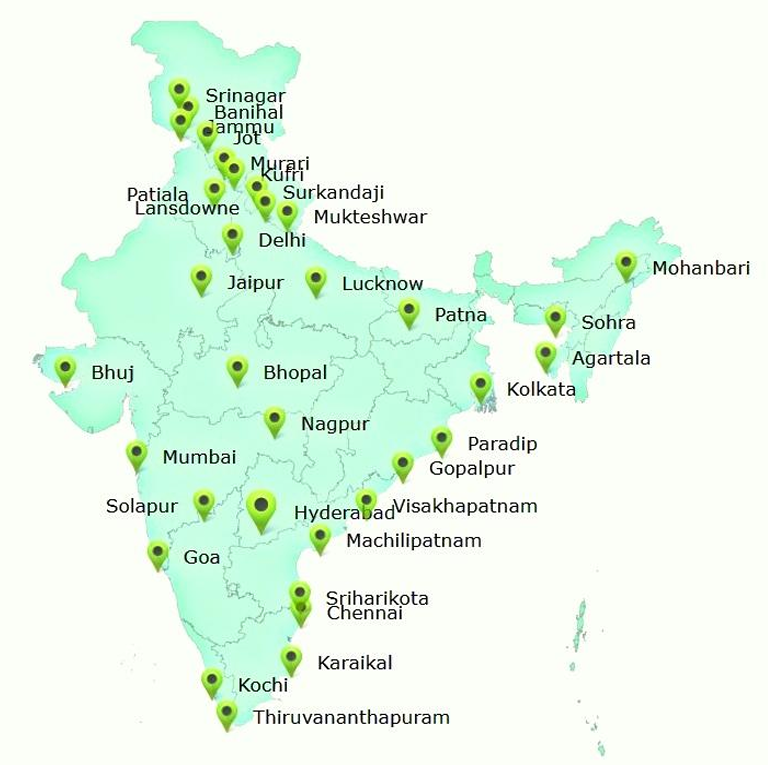
FIGURE 1: Meteorological radar network across India.
2. EMI EMC Overview
Electromagnetic interference (EMI) is a ubiquitous issue that affects a wide range of radar and telecommunication systems [4]. The rapid advancement of electronics has led to the development of modern radar systems with complex structures that operate at high power and frequencies in the GHz range [5, 6]. Weather radars, in particular, transmit and receive microwave pulses, making them susceptible to distortions in the radar signal picture when surrounding objects transmit over the same frequency range.
Interference can occur when microwaves are emitted by any other devices within a similar frequency range as weather radars that disrupt the radar's measurement capabilities and produce characteristic interference patterns such as spokes, dots, and stripes in the output images. EMI is a broad phenomenon that encompasses both inter-system and intra-system problems, making it a significant challenge in the design and operation of radar and telecommunication systems.
2.1. EMI
EMI is characterized as the disruption of electronic devices, electrical systems, or radiofrequency systems by electromagnetic energy, which can occur through electrostatic conduction, electromagnetic induction, or coupling.
This disturbance can lead to degradation in circuit performance, potentially resulting in absolute malfunction. EMI can manifest in two forms: radiated and conducted.
Radiated EMI, also referred to as radio-frequency interference (RFI), propagates as radio waves, while conducted EMI occurs when an external electromagnetic field induces an unintended current in a physical path, such as a wire or cable, which is then carried to the affected device. This can lead to unwanted electromagnetic coupling, compromising the device's functionality. While induction is the cause of radiated EMI, physical contact between the conductors is the reason for conducted EMI. Inductive coupling takes place when the victim and source are in close proximity to one another (typically not more than a wavelength).
2.2. EMI sources
The operation of radar systems can be compromised by EMI arising from interactions between electromagnetic fields. The occurrence of EMI can be attributed to three primary elements [7]:
- The emitter, which generates undesired interferences.
- The perturbed equipment, which responds to these interferences.
- The coupling channel, which transmits the interference signal from the source to the receiver.
Radar equipment is susceptible to various interference sources, including both internal and external sources. Internal sources include sudden voltage and power fluctuations, element coupling, and electrical/electronic circuit interface, which can lead to EMI.
External sources can be categorized into two types:
- Natural sources, which include events such as precipitation, solar flares, thunderstorms, snow, and cosmic rays, can trigger EMI in electrical circuits. These sources significantly impact systems used in radio astronomy, space applications, aerospace applications, ground-based radar, and telecommunication applications. As these events are beyond human control, extra precautions must be taken when designing electrical circuitry.
- Man-made sources, which include circuit components that can disrupt the operation of adjacent devices or components through conduction (via wires and cables) or radiation (via electromagnetic fields). Examples of man-made sources include mobile phones, computers, radios, medical equipment, X-ray machines, microwave ovens, power cables, ignition systems, and many other items that can generate unintentional interference. These sources affect a wide range of electronic systems.
2.3. EMC
It is the potential of a device to function as intended amidst other electrical devices or EMI sources without producing interference for the other devices. When a device does not adversely affect other devices and systems due to its electromagnetic environment effect, it is regarded to be electromagnetic compatibility (EMC)-compliant.
EMC addresses three primary issue classes:
- Emission, which encompasses the intentional or accidental generation and discharge of electromagnetic radiation into the environment by a source. EMC investigates unwanted emissions and explores strategies for mitigation.
- Susceptibility, which refers to the possibility of electrical equipment (the "victim") malfunctioning or failing when exposed to undesired emissions or RFI.
- Immunity, which is the ability of equipment to perform its intended functions without impairment in the presence of RFI. The process of "hardening" equipment involves both susceptibility and immunity considerations, aiming to enhance the equipment's resilience against EMI.
3. EMI Effects on Radar Parameters
Radar systems are prone to severe EMI among their internal components [8], which can compromise their stability and consistency. Therefore, EMC analysis is crucial to ensure reliable operation. To prevent harmful EMI between radar equipment and other services, specific techniques must be employed. There are two primary ways that the radar system and interfering signals from other services can couple through EMI: Intermodulation generation, leading to spurious signals and spikes and interference from emissions in the receiver's intermediate frequency (IF) passband, causing desensitization, performance deterioration, and ultimately, lower quality radar data output. Moreover, radar frequency and peak power are critical factors in mitigating EMI.
- Frequency: Regardless of weather conditions, attenuation, or power loss increases with increasing radar wave frequency. Consequently, lower radar frequencies (longer wavelengths) are generally preferred for greater detection ranges. However, EMI can cause pulse shape distortion by introducing droop [6].
- Peak power: Doubling the peak power results in approximately 25% more range for the radar. Nevertheless, EMI can introduce noise, reducing overall power quality.
- Pulse length: The longer the pulse duration, the more power the radar will radiate, and consequently, its detection range will be extended. Unless a target is separated by over fifty percent of the pulse duration, two nearby targets on the same bearing cannot be distinguished as two distinct targets on the plan position indicator (PPI). The targets would need to be more than 164 yards apart for radar with a 1-microsecond pulse duration to appear as separate echoes on the PPI. EMI alters the pulse duration.
- Receiver sensitivity: Greater detection ranges are possible with more sensitive receivers. EMI can be seen in the form of clutter.
4. Control Measures for EMI
Control measures for the EMI are integrated into the receiver design from the outset. EMC hardening materials are included during the manufacturing stage. The use of appropriate EMI gaskets, shielded cables, and connectors has achieved the necessary EMC hardening, as demonstrated during receiver testing. The crucial considerations at the design and production stages are listed below:
- Rubber gaskets consisting of wire mesh are utilized in each cast box to provide effective electromagnetic shielding and best possible environmental sealing.
- Grounding: Digital and radio frequency signals are connected independently to their respective grounds, which are then coupled at a single point to the chassis of the modules. Power supply and their returns are routed separately up to the regulators, minimizing ground loops and common ground impedance issues.
- Feed-through filtering: Fixed bias and power supply lines to the circuits are connected by means of feed-through filters. Double regulatory circuit and filters can be applied to power supply lines, reducing the conductivity of interference via supply lines.
- Shielded cables: Power supply cables, inter-connecting wires, signal cables are routed with metallic shielded enclosures, with the shielding kept at zero potential to eradicate pickups. To provide better isolation among the vulnerable areas of RF signals, semi-rigid cables can be used.
- Filtering: Low-pass filters are predominantly used in radar equipment to restrain transient noise from inductive loads. Connecting the power input to the filter reduces EMI from the electrical network. Filters, comprising inductors and capacitors, are often configured in "π" shape, "T" type structure, or "L" form to control lower and center frequency EMI.
5. Observed Interference
In India, the Doppler weather radar (DWR) operates within the 2.7 to 3.0 GHz frequency range of the S-band. The prime sources of interference are interference from wireless networks operating at the adjacent frequency and from other radars operating at similar frequency bands, such as airport surveillance radar (ASR) systems, which function in the 2.7–2.9 GHz range. Since the sensitivity of the DWR receiver is very high, the interferences are often picked up by the receiver [9]. Figure 2 shows the inferences received at the antenna receiver terminal around the radar station. Although the out-of-band attenuation was rejected by the filter circuit (Figure 3), available within the radar, but the attenuation from other sources working within the same frequency band was captured by the radar. Figures 4–11 show the interfering clutter signature as Integrated Radar Imaging System (IRIS) in the radar images.
.png)
FIGURE 2: Interference at the receiver end.
.png)
FIGURE 3: Filtered output of receiver.
.png)
FIGURE 4: Interference observed at Delhi.
.png)
FIGURE 5: Interference observed at Patiala.
.png)
FIGURE 6: Interference observed at Bhopal.
.png)
FIGURE 7: Interference observed at Karakail.
.png)
FIGURE 8: Interference observed at Bhuj.
.png)
FIGURE 9: Interference observed at Patna.
.png)
FIGURE 10: Interference observed at Mumbai.
.png)
FIGURE 11: Interference observed at Kochi.
6. Mitigation Techniques
- Use of dual frequency, which will cause different scattering of the signal.
- Use of phased array radar consisting of 1000s of antennas to receive data instead of a single antenna DWR.
- Use of dual-polarized radar that can send and receive pulses in both vertical and horizontal directions. Consequently, measurements of the targets' horizontal and vertical dimensions are provided by the returning frequencies, allowing for more accurate estimations of clutter relative to genuine targets.
- Use of SAW filter: The ability of these filters to offer large rejection bandwidths is one of their advantages. As a result, undesirable frequencies that are near the intended signal’s frequency range can be successfully filtered out using these filters. They offer high selectivity along with low insertion loss [10].
- Use of a variable or adjustable noise filter, adjustable from ray to ray to optimize noise reduction.
- Solid-state transmitters are designed to provide improved spectrum performance, characterized by reduced sidebands and high-order harmonics, resulting in a cleaner spectrum [11].
- A blind zone can be established around the cluttered region, and multiple pulses of varying pulse size, repetition times, and frequencies can be used to the blind zone and produce a uniform minimum detectable signal.
- It is crucial that the meteorological organization participate in frequency management, prospectively, to prevent situations like these in the future [1].
Acknowledgments
The present study was made possible through the encouragement and support provided by the India Meteorological Department, which the authors gratefully acknowledge. The authors' sincere appreciation is extended to all Meteorological officials at IGI Airport, New Delhi, for the immense support they received throughout the study.
References
- E. Saltikoff et al., “The threat to weather radars by wireless technology,” Bull. Amer. Meteor. Soc., vol. 97 no. 7, pp. 1159-1167, Jul 2016.
- M. Vaccarono, C. V. Chandrasekar, R. Bechini and R. Cremonini, "Survey on Electromagnetic Interference in Weather Radars in Northwestern Italy," Environments, vol. 6, no. 12, pp. 126, Dec 2019.
- M. A. Vega, V. Chandrasekar, J. Carswell, R. M. Beauchamp, M. R. Schwaller and C. Nguyen, “Salient features of the dual-frequency, dual-polarized, Doppler radar for remote sensing of precipitation,” Radio Sci., vol. 49, no. 11, pp. 1087-1105, Oct 2014.
- G. S. Prasad and N. Shanmugam, "EMC issues of radar receiver-a case study," in Proc. Proceedings of the International Conference on Electromagnetic Interference and Compatibility (IEEE Cat. No.02TH8620), Bangalore, India, 2002, pp. 247-250.
- J. Meng, J. Cai and C. Han, "Control methods of EMI for modern radar," in Proc. 2002 3rd International Symposium on Electromagnetic Compatibility, Beijing, China, 2002, pp. 714-717.
- F. H. Sanders, R. L. Sole, B. L. Bedford, D. Franc and T. Pawlowitz, “Effects of RF Interference on Radar Receivers,” U.S. Dept. of Commerce, USA, NTIA Report TR-06-444, Sep 2006.
- P. Mathur and S. Raman, “Electromagnetic Interference (EMI): Measurement and Reduction Techniques,” J. Electron. Mater., vol. 49, pp. 2975-2998, Feb 2020.
- S. R. Ranade, "Designing for electromagnetic compatibility in pulsed high power transmitters: a case study," in Proc. 8th International Conference on Electromagnetic Interference and Compatibility, Chennai, India, 2003, pp. 109-114.
- International Telecommunication Union, “Assessment of interference to radars operating within the 2 700-2 900 MHz band from broadband wireless systems operating in adjacent frequency bands” Geneva, Switzerland, Report ITU-R M.2316-0, 2015.
- J. Golden, "Clutter mitigation in weather radar systems filter design & analysis," in Proc. Proceedings of the Thirty-Seventh Southeastern Symposium on System Theory, 2005. SSST '05., Tuskegee, AL, USA, 2005, pp. 386-390.
- N. Bharadwaj and V. Chandrasekar, “Wideband Waveform Design Principles for Solid-State Weather Radars,” J. Atmos. Oceanic Technol., vol. 29, no. 1, pp. 14-31, Jan 2012.
Contact Us

 This work is licensed under a Creative Commons Attribution 4.0 International License. Copyright © 2026 LANASH SCIENCE Inc, All Rights Reserved.